Switching power supplies have penetrated into various industries in the national economy. Designers either design their own power supplies or purchase power modules, but these power supplies are inseparable from the various circuit topologies of the power supply. This article first introduces the three basic topologies of switching power supply: Buck, Boost, Buck-Boost, and simply combines these three topologies, and get very clever circuits, such as: positive and negative output power, bidirectional power Etc., can meet certain special needs such as op amp power supply, battery charge and discharge.
2, switching power supply basic topology
The three basic topologies of switching power supply are: Buck, Boost, and Buck-Boost. Most of the switching power supplies use these basic topologies or their corresponding isolation modes. The following is a brief introduction of the inductor continuous mode.
2.1 Buck step-down type
The Buck step-down circuit topology, sometimes called the Step-down circuit, has a typical circuit structure as shown in Figure 1:
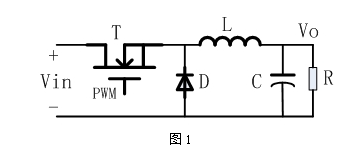
The working principle of the Buck circuit is:
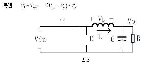
When the PWM drive high level causes the NMOS transistor T to be turned on, the conduction voltage drop of the MOS transistor is ignored, equivalent to FIG. 2, the inductor current rises linearly, and the forward volt-second of the inductor when the MOS is turned on is:
When the PWM is driven low, the MOS transistor is turned off, the inductor current cannot be abrupt, and the loop is formed by the freewheeling diode (ignoring the diode voltage), and the output load is supplied. At this time, the inductor current drops, as shown in Figure 3 below, when the MOS is turned off. The inductance reverse volts is:
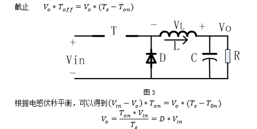
D is the duty cycle, 0
2.2 Boost boost type
The Boost boost circuit topology, sometimes referred to as a step-up circuit, has a typical circuit structure as shown in Figure 4:
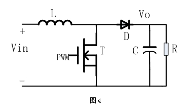
Similarly, according to the analysis method of the Buck circuit, the working principle of the Boost circuit is:

2.3 Buck-Boost polarity reversal lifting type
The Buck-Boost circuit topology, sometimes called InverTIng, has a typical circuit structure as shown in Figure 5:
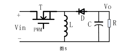
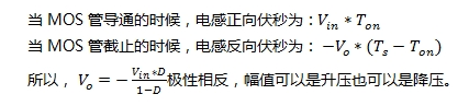
Similarly, according to the analysis of the Buck circuit, the Buck-Boost circuit works as follows:
For the 22kV Oil Immersed Power Transformer, we can produce capacity upto 420MVA. We use the best quality of raw material and advance design software to provide low noise, low losses, low partial discharge and high short-circuit impedance for power transformer.
Our power transformer are widely used in national grid, city grid, rural grid, power plant, industrial and mining enterprise, and petrochemical industry.
220Kv Transformer,220Kv Power Transformer,High Quality Power Transformer,Oil Immersed Transformer
Hangzhou Qiantang River Electric Group Co., Ltd.(QRE) , https://www.qretransformer.com