If you're looking to become a skilled inverter repair technician, understanding the basics of inverter technology is essential. It's not just about knowing how things work—it's about being able to diagnose and fix problems efficiently. In this guide, I’ll walk you through the fundamental components and circuits involved in inverter operation. If you find any inaccuracies or have suggestions, feel free to share them. And if you found this helpful, I’d really appreciate a like or a comment to keep me motivated!
Getting Started with Inverter Repair: Circuit Analysis
To effectively repair an inverter, it’s not enough to just know the basic theory. You need a deep understanding of its main circuits. The core components include the rectifier circuit, current limiting circuit, filter circuit, braking circuit, inverter circuit, and detection sampling circuit. Figure 2.1 shows the overall structure.
Understanding the Basic Circuit Diagram of an Inverter
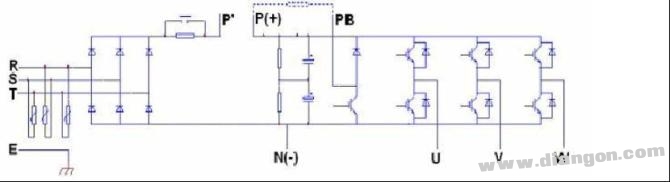
Most general-purpose inverters are AC-DC-AC type, meaning they convert AC to DC and then back to AC. The core of the inverter is its main circuit, which typically includes a rectification stage (AC to DC), a DC filtering stage, and an inverter stage (DC to AC). Additional components such as a current limiting circuit, braking circuit, and control circuit also play key roles.
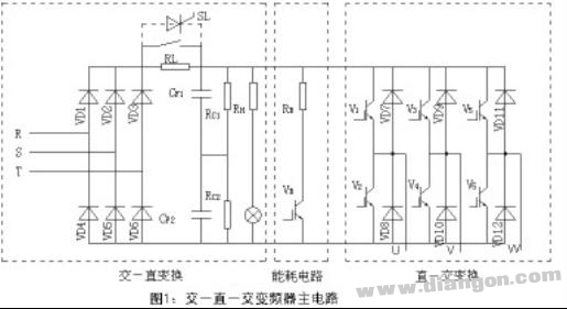
1) Rectifier Circuit
The rectifier circuit in a general-purpose inverter usually consists of a three-phase bridge rectifier. Its main function is to convert the incoming AC power into DC power for use by the inverter and control circuits. This circuit is often preceded by an absorption capacitor and a varistor network, which help protect against high-frequency harmonics and voltage surges from the grid.
When the input voltage is 380V, the maximum reverse voltage across the rectifier devices is typically between 1200V and 1600V, and the maximum rectified current is around twice the rated current of the inverter.
2) Filter Circuit
The filter circuit plays a crucial role in smoothing out the pulsating DC output from the rectifier. Since the load is usually an inductive motor, reactive power is constantly exchanged between the motor and the DC link. The filter capacitors store and release this energy, stabilizing the DC voltage and reducing ripple.
Large aluminum electrolytic capacitors are commonly used in the DC filter circuit. These capacitors are connected in series and parallel to achieve the required voltage rating and capacitance. To ensure even voltage distribution, resistors are often added in parallel to balance the voltage across each capacitor.
3) Inverter Circuit
The inverter circuit is responsible for converting the DC power from the filter stage into adjustable AC power. This is achieved using power switching devices like IGBTs or GTRs arranged in a three-phase bridge configuration. By controlling the on/off timing of these switches, the frequency and voltage of the AC output can be adjusted.
Many small and medium-sized inverters use integrated modules that combine the rectifier, inverter, sensors, and protection circuits in one unit. For example, the IPM50RSA120 from Mitsubishi or the 7MBP50RA060 from Fujitsu integrate multiple functions into a single module, improving reliability and performance.
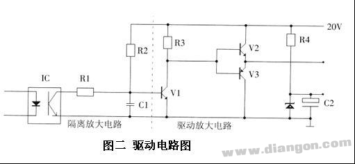
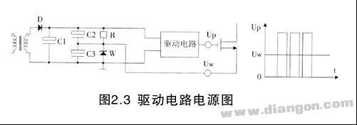
4) Driving Circuit
The driving circuit is responsible for amplifying and isolating the PWM signals generated by the microcontroller to drive the power switches in the inverter. These circuits are critical for ensuring safe and efficient operation of the inverter. Some inverters use dedicated driver modules, while others rely on custom-built driver circuits.
5) Protection Circuit
Inverters are equipped with various protection mechanisms to prevent damage from overvoltage, undervoltage, overcurrent, and overheating. These can be implemented through hardware circuits or software-based monitoring systems. A typical overcurrent protection circuit includes current sampling, signal isolation, and amplification stages to detect and respond to faults quickly.
As you continue learning about inverter repair, remember that practice and hands-on experience are just as important as theoretical knowledge. Keep experimenting, stay curious, and always look for ways to improve your skills. Happy repairing!
Cordline Switches,Electrical Switch, Rocker Switch, Foot Switch, Hand Switch, On-Off Rocker Switches
Jiangmen Krealux Electrical Appliances Co.,Ltd. , https://www.krealux-online.com