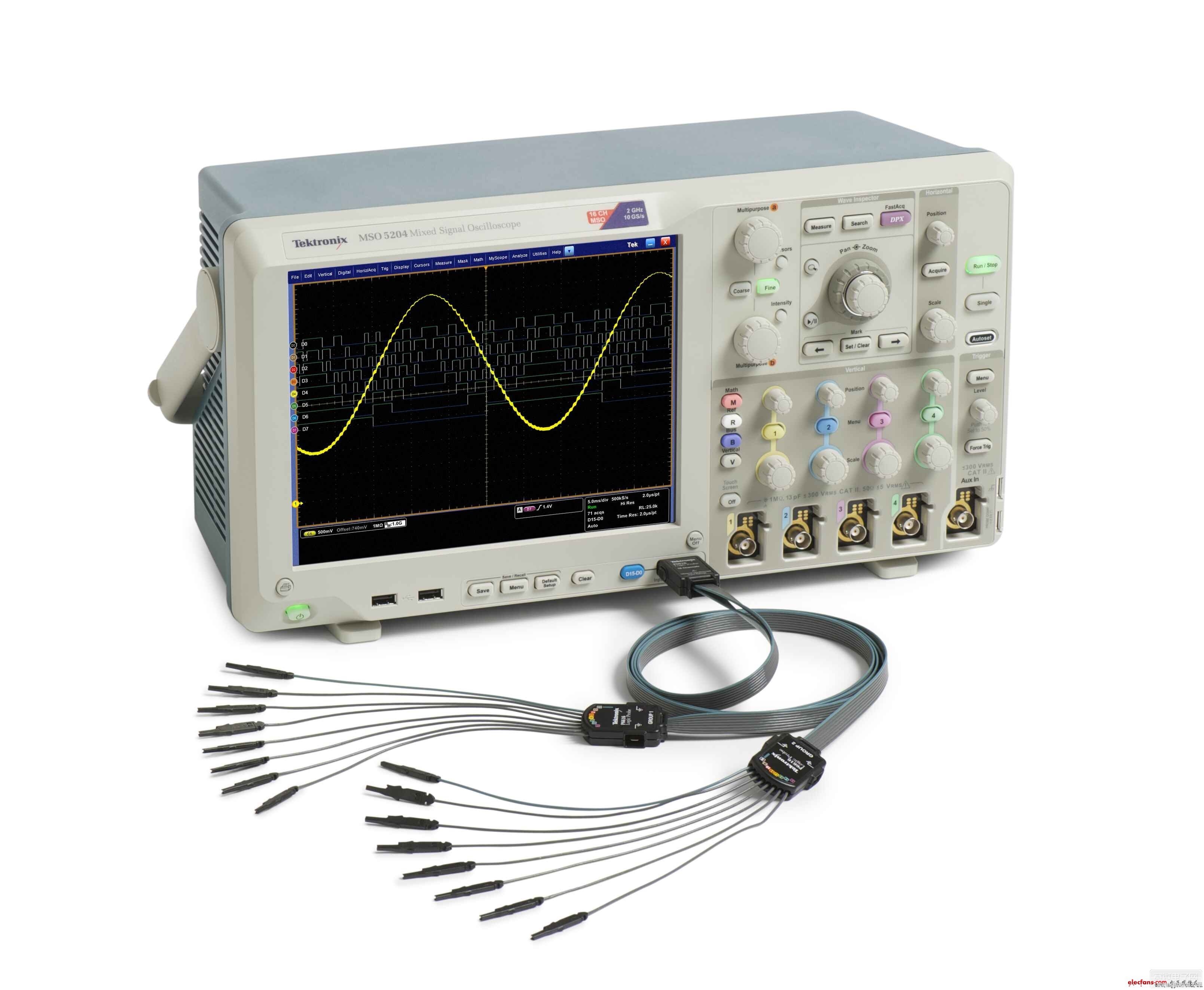
How do you measure voltage using an oscilloscope? An oscilloscope, whether virtual or digital, is a powerful tool for analyzing signal waveforms over time. It allows you to observe various types of signals, including measuring voltage, current, and more. The display system of a digital oscilloscope consists of the cathode ray tube (CRT) and its control circuitry. The CRT contains an electron gun, a fluorescent screen, and a deflection system. Any measurement performed with an oscilloscope essentially involves measuring voltage. This article will explain how to measure voltage using an oscilloscope and highlight important safety considerations during use.
Oscilloscopes can be either analog or digital. Both types are suitable for most electronic applications, though they have different strengths and limitations depending on the specific use case. Oscilloscopes are widely used to measure the amplitude of various waveforms, such as DC voltages, sinusoidal voltages, and pulsed or non-sinusoidal signals. They can also measure the voltage amplitude at different points in a pulse waveform, which is something no other voltage measurement device can match.

First, the method of measuring voltage by oscilloscope
Direct Measurement Method
The direct measurement method involves measuring the height of the voltage waveform directly from the screen and converting it into a voltage value. When quantifying the measured voltage, it’s common to set the Y-axis sensitivity knob to the "calibrate" position so that the voltage value can be calculated directly from the "V/div" scale and the vertical coordinate occupied by the signal. This method is also known as the scale method.
(1) Measuring DC Voltage
Set the Y-axis input coupling switch to "Ground" and the trigger mode to "Auto" to display a horizontal line representing the zero reference. Then, switch the coupling to "DC" and apply the measured voltage. The signal will cause a vertical displacement H on the screen. The measured voltage is the product of the "V/div" setting and H.
This method is simple but prone to errors due to reading mistakes, parallax, and internal oscilloscope inaccuracies like those from the attenuator or deflection system.
(2) Measuring AC Voltage
Set the Y-axis coupling to "AC" to display only the AC component. For very low-frequency signals, use the "DC" position instead. Center the waveform on the screen, adjust the "V/div" to fit the waveform within the visible area, and measure the peak-to-peak voltage by multiplying the "V/div" value by the number of divisions the waveform spans vertically. If using a probe, remember to multiply by the probe's attenuation factor (usually 10x).
For example, if the "V/div" is set to 0.2 V/div and the waveform spans 5 divisions, the peak-to-peak voltage is 1 V. If a 10x probe is used, the actual voltage is 10 V.
2. Comparative Measurement Method
The comparative method uses a known standard voltage to compare with the measured signal. First, connect the unknown voltage to the Y-axis and adjust the sensitivity so the waveform is clearly visible. Keep the settings unchanged. Then, replace the unknown voltage with a known standard voltage and adjust it until it matches the measured signal in amplitude. The standard voltage now equals the measured voltage, improving accuracy by reducing system-related errors.
Second, Oscilloscope Usage Precautions
To ensure operator safety and accurate measurements, always follow proper procedures when using an oscilloscope. Here are some key precautions:
1. When measuring high-voltage floating signals (such as switching power supplies, UPS systems, or inverters), use a high-voltage differential probe like the DP100 to avoid damaging the oscilloscope or endangering the user.
2. Adjust the brightness and focus knobs to minimize the spot size, ensuring a clear waveform and reducing measurement errors. Avoid leaving the spot stationary on the screen, as this can damage the phosphor coating.
3. All ground connections—oscilloscope chassis, BNC socket outer ring, probe ground wire, and AC power ground—must be properly connected. Failure to do so can create dangerous potential differences between the device under test and ground, posing a serious risk.
4. Ensure all devices, including oscilloscopes, signal sources, and power supplies, are grounded to a common point to prevent noise and interference.
5. Some oscilloscopes, like the TDS200/TDS1000 series, should not be used to measure high-voltage floating signals (e.g., AC220V) directly, as this can damage the instrument.
Additional Tips for Oscilloscope Use
1. Avoid frequent power cycling of thermal instruments like oscilloscopes to prolong their lifespan.
2. If external interference affects the waveform, make sure the oscilloscope is properly grounded.
3. Before turning off the power, reduce the brightness to a minimum to protect the screen.
4. Keep the brightness of the waveform moderate to avoid eye strain and screen damage.
5. Never exceed the maximum input voltage rating (typically 400 V). If the Y-input is left open, it may pick up electromagnetic interference, which should be avoided.
Measuring voltage with an oscilloscope is a fundamental skill for engineers and technicians. Understanding the methods and safety practices ensures accurate and safe measurements. While oscilloscopes vary in design and features, the basic principles remain similar across models, with variations mainly in bandwidth and sensitivity.
4 port epon olt,8 port epon olt,2 port epon olt,mini epon olt,16 port epon olt
Shenzhen Runtop Technology Co.LTD , https://www.runtoptech.com