Motor Multi-Protection Control Circuit
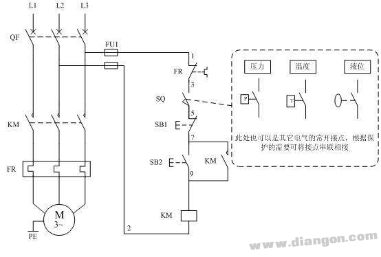
The motor multi-protection starting circuit is designed to ensure that the motor can only start when all peripheral auxiliary equipment meets the required conditions. For example, in the diagram, SQ represents a position switch used for safety protection. If the auxiliary device hasn't reached its designated position, the motor will not start. This system can also be adapted for other types of protection, such as pressure, temperature, or liquid level control. When multiple protections are needed, the normally open contacts of these devices are connected in series to ensure all conditions are met before the motor starts.
During the starting process, the QF switch is closed, but the SB2 start button remains inactive until the SQ switch's normally open contact is closed. Once the auxiliary device reaches the correct position, the contact closes and allows the SB2 button to function. If the position changes during operation, the SQ contact opens immediately, de-energizing the KM contactor coil and disconnecting the motor's power supply. This ensures the motor stops safely, providing effective protection.
Common Malfunctions
1. Motor won't start:
- Check if the fuse FU1 in the control circuit is functioning properly (use a multimeter to test, it should show continuity).
- Verify if the thermal relay's FR contact is properly connected or if it has tripped (should show continuity at three points when tested).
- Ensure the contacts of the peripheral devices are correctly connected (test should show continuity at five points).
2. SB1 stop button not working:
If the stop button doesn't work, there might be a wiring error. For instance, if the contactor is connected to the 7th line of the self-locking circuit, the SB1 may not function as expected.
3. No self-locking function:
- First, check if the contactor's auxiliary normally open contact is making proper contact.
- Second, verify if the contactor’s contacts are incorrectly wired—such as using a normally closed contact instead of a normally open one.
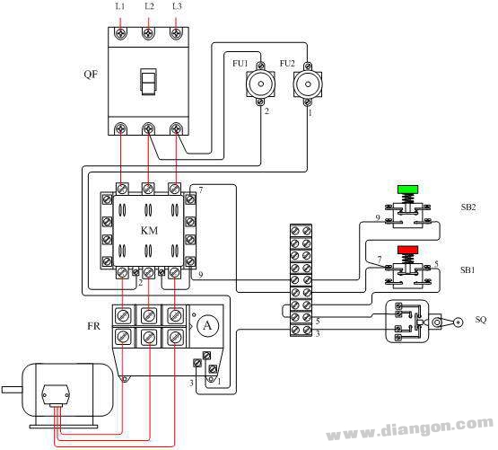
Motor Multi-Protection Control Circuit Wiring Diagram
SVLEV provide 4- and 8-channel models with 1 to 10 A current ratings offer you the flexibility you need for setting the nominal current to suit your needs.
At the same time, it can also query the operating parameters of the power grid in real time. When the power grid fails, it can quickly interrogate and repair the fault. For example, svlec electronic circuit breaker and intelligent power distribution board can monitor the power and fully control the system status. The distribution board provides fault protection for system components and switching power supplies. It has intelligent shutdown, early warning, remote reset and single-channel management functions. This ensures the maximum operating range of the system.At the same time, the intelligent circuit breaker is smaller, easier to install and saves space. The modular function can meet users' application needs in different scenarios, and installation is also easier. In addition, intelligent circuit breaker is also safer.

4-channel electronic circuit breakers,8-channel electronic circuit breakers,Circuit Protection
Kunshan SVL Electric Co.,Ltd , https://www.svlelectric.com