If you're aiming to master inverter repair, having a solid understanding of its basic principles is essential. This guide will walk you through the fundamental concepts and key circuits involved in inverter maintenance. I welcome any corrections or feedback you might have. If you find this helpful, feel free to give it a thumbs up or share it with others who may benefit.
Getting Started with Inverter Repair: Circuit Analysis
To effectively repair an inverter, it's not enough to just understand the basics. You also need a deep knowledge of the main circuits that make up the system. The core components include the rectifier circuit, current limiting circuit, filter circuit, braking circuit, inverter circuit, and detection sampling circuit. Figure 2.1 illustrates the overall structure.
Basic Circuit Diagram of an Inverter
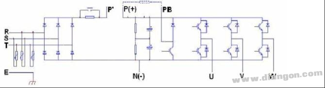
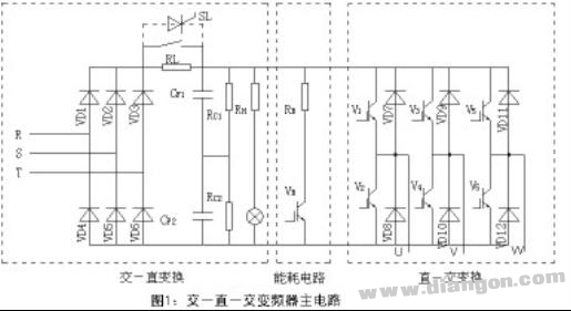
Most general-purpose inverters are AC-DC-AC type. The main circuit (as shown in Figure 1.1) consists of a rectification stage (AC to DC), a DC filter stage (energy storage), and an inverter stage (DC to AC). Additional elements like a current limiter, braking circuit, and control circuit are also part of the system.
1) Rectifier Circuit
The rectifier circuit typically uses a three-phase bridge configuration. Its purpose is to convert the incoming AC power into DC for use by the inverter and control circuits. It’s usually preceded by an absorption capacitor and varistor network to protect against surges and high-frequency noise. When the input voltage is 380V, the rectifier device must handle a reverse voltage of around 1200–1600V and a current twice the inverter’s rated value.
2) Filter Circuit
The filter circuit smooths out the pulsating DC from the rectifier. Since the load is an inductive motor, reactive power exchange occurs between the motor and the DC link. The filter capacitors help buffer this energy. These capacitors are often connected in series and parallel to meet the required voltage and capacitance. To ensure even voltage distribution, resistors are added in parallel to balance the capacitors’ characteristics, which can affect the inverter’s lifespan.
3) Inverter Circuit
The inverter circuit converts the DC power into adjustable AC output. A typical setup includes six power switches (like IGBTs or GTRs) arranged in a three-phase bridge. By controlling the switching sequence, the frequency and voltage of the output can be adjusted. Many small to medium-sized inverters use integrated modules that combine rectification, inverting, and protection functions within a single unit.
4) Freewheeling and Buffer Circuits
A freewheeling circuit helps manage regenerative energy from the motor during deceleration. It also prevents short circuits caused by simultaneous switching on the same bridge arm. Additionally, buffer circuits are used to protect the inverter from unexpected faults such as overvoltage or overheating.
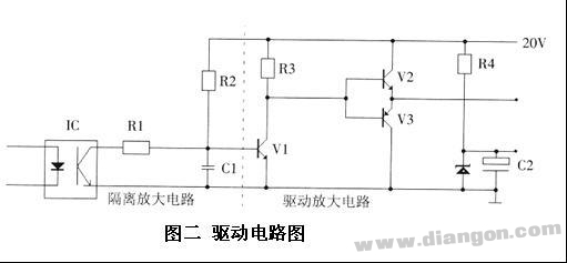
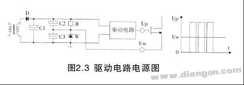
5) Driving Circuit
The driving circuit receives PWM signals from the CPU and amplifies them to drive the power switches. Some inverters use dedicated driver modules, while others rely on custom-built circuits. A typical design includes isolation, amplification, and power supply stages for each switch.
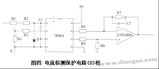
6) Protection Circuit
Inverters are equipped with various protection mechanisms to minimize damage during faults. These include overcurrent, overvoltage, and thermal protection. Many modern inverters integrate these protections into their modules, reducing the need for external circuits. A common example is the overcurrent detection circuit, which samples the current, isolates the signal, and amplifies it for processing.
Understanding these components and their roles is crucial for anyone looking to dive into inverter repair. Whether you're a beginner or an experienced technician, a strong foundation in inverter theory and practical skills will greatly enhance your ability to diagnose and fix issues efficiently.
Cable Box,Junction Boxes,Cable Connection Box,Waterproof Cable Box,Electrical Junction Boxes
Jiangmen Krealux Electrical Appliances Co.,Ltd. , https://www.krealux-online.com