Application brief
Energy consumption is a common problem facing the world, and many industries are working to address this issue by implementing safer, cleaner, more efficient, and lower-cost power solutions. The growing popularity of hybrid and electric vehicles, solar energy and wind energy is the result of this trend. All of these solutions have one thing in common: lithium-ion batteries. Due to the rapid growth of these fields, lithium-ion batteries will play a more important role in energy conservation.
Lithium-ion battery manufacturing processes are complex, including electrode production, stacking structures, and cell assembly. An electrical test is then performed to assess battery capacity and performance. This is followed by an electrical test to assess the capacity of the battery at work, ie the rating. For these electrical tests in the manufacture of lithium-ion batteries, high power, high efficiency and high precision test equipment are required. ADI's solutions based on the AD8450/1 and ADP1972 were introduced for this purpose.
System design considerations
effectiveness
The capacity of lithium-ion batteries in laptops, cell phones, and similar portable devices is typically small, typically a few hours. However, the capacity of lithium-ion batteries used in vehicles or energy storage is much higher, usually around tens or even hundreds of amps. Linear test equipment for small-capacity batteries, if used for high-capacity battery testing, will consume a lot of power during the charging phase, resulting in inefficiencies and serious thermal problems in the hardware design of the device. The ADI AD8450/1 and ADP1972 solutions are based on a PWM architecture that helps solve this problem.
The ADI PWM architecture also helps to charge more battery power back to the grid or other test channels for charging. This is an environmentally friendly and efficient solution compared to a linear architecture that discharges battery energy to a resistive load.
Precision
In order to obtain accurate lithium-ion battery capacity, it is necessary to accurately measure the current and voltage in both the charging and discharging modes. Combining precision ADCs, DACs, and other devices in the system, ADI's solutions based on the AD8450/1 and ADP1972 enable high-accuracy measurements and settings.
Low system cost
• Higher switching frequency supports the use of smaller, lower cost power components such as inductors and capacitors
• Energy recycling helps reduce operating costs
• AD8450/1 is more accurate, reducing thermal management costs and simplifying control loop design
• The AD8450/1 features a unique instrumentation amplifier design that halve calibration time during manufacturing and longer performance guarantees
• Integrated solution for smaller system size and lower equipment and maintenance costs
ADI solution
System Block Diagram
Below is a block diagram of the system from DC bus to battery, including microcontroller, analog front end and controller, PWM controller, high voltage MOSFET driver, power stage (MOSFET, inductor, capacitor, shunt resistor), voltage/current read (ADC) ) and voltage/current settings (DAC).
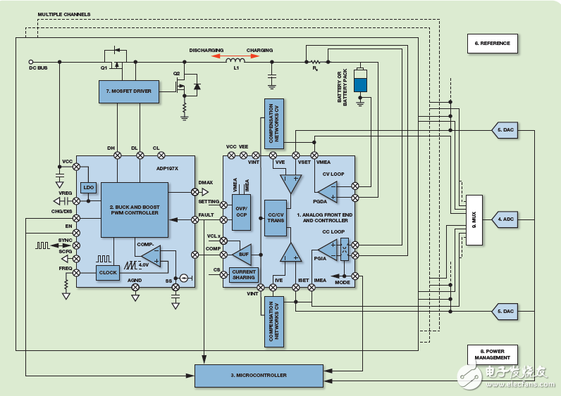
Note: The above signal chain represents the channel board design from the DC bus to the battery. The technical requirements of the module can vary, but the products listed in the table below represent ADI solutions that meet some of the requirements.
1. Analog front end and controller AD8450/AD8451
2. Buck and Boost PWM Controller ADP1972
3. Microcontroller ADuC7060/ADuC7061
4. Analog to Digital Converter AD7173-8/AD7175-2
5. DAC AD5686R/AD5668/ AD5676R
6. Voltage Reference ADR3450/ADR4550
7. MOSFET Driver ADuM7223
8. Power Management ADP2441/ADP7102/ ADM8829
9. Multiplexer ADG528F/ADG5408/ ADG658/ADG1406
How the system works
The above picture mainly contains two functions: one is to charge the battery, and the other is to discharge the battery, which is determined by the mode signals of AD8450/1 and ADP1972. There are two modes for each function: constant current (CC) mode and constant voltage (CV) mode. Two DAC channels control the CC and CV set points. The CC set point determines how much current is in the loop in CC mode for both charging and discharging functions. The CV set point determines the battery potential at which the loop enters the CV from the CC, as well as the two functions of charging and discharging.
The precision analog front end and controller AD8450/1 measures the battery voltage using the internal differential amplifier PGDA and measures the current on the battery using the internal instrumentation amplifier PGIA and an external shunt resistor (RS). It then compares the current and voltage to the DAC set point through an internal error amplifier and an external compensation network (used to determine whether the loop function is CC or CV). After this module, the output of the error amplifier enters the PWM controller ADP1972 to determine the duty cycle of the MOSFET power stage. Finally, the inductors and capacitors that make up the complete loop. The instructions in this section address both charging and discharging functions because the ADP1972 is a buck and boost PWM controller.
In this scenario, the ADC obtains a reading of the loop voltage and current, but it is not part of the control loop. The scan rate is independent of the performance of the control loop, so an ADC can measure the current and voltage of a large number of channels in a multi-channel system. The same is true for DACs, so multiple channels can be set up using low cost DACs. In addition, a single processor only needs to control CV and CC setpoints, operating modes, and management functions, so it can interface with many channels.
System performance
Analog Devices has produced the ADP1972 and AD8450 demo boards as shown below to verify their efficiency and accuracy. For this asynchronous buck and boost power system, the DC bus input is 12 V and the maximum charge/discharge current is 20 A.
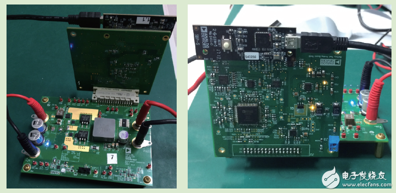
Efficiency: The demonstration board is approximately 90% efficient at maximum ratings, 20 A CC mode (both charging and discharging) and 3.3 V load. To achieve this, external diodes, shunt resistors, inductors, and MOSFETs are optimized.
Accuracy: After calibrating the initial accuracy, the accuracy of the current includes temperature drift, linearity over the full current range (0 A to 20 A), short-term stability (noise), and CMRR over the full voltage range (0 V to 3.6 V). As a result of the demonstration on the demo board, the typical current accuracy of this ADI solution is less than 0.01% (25°C ± 10°C). A similar analysis can be performed on the voltage accuracy, which is verified to be below 0.01%.
Residual Current Circuit Breaker
RCCB named Residual Current Circuit Breaker. When there is human electricity shock or if the leakage current of the line exceeds the prescribed value, Residual current circuit breaker/RCCB(without over-current protection) will cut off the power rapidly to protect human safety and prevent the accident due to the current leakage. The rccb switch which made from Korlen electric can be used as infrequent changeover of the line in normal situation.
Korlen electric ---- the rccb switch manufacturer,produces types of Residual Current Circuit Breaker. It is applicable to industrial site, commercial site, tall building and civil house.
Residual Current Circuit Breaker,Ac Residual Current Circuit Breaker,Miniature Residual Current Circuit Breaker,Residual Current Electrical Circuit Breaker
Wenzhou Korlen Electric Appliances Co., Ltd. , https://www.zjthermalrelay.com