What is power factor compensation and what is power factor correction:
Power factor compensation: In the 1950s, an improved method was proposed for the inconsistent power supply efficiency caused by the different phases of the voltage and current of the AC electrical appliance with inductive load (Fig. 1) (due to the current hysteresis of the inductive load) The voltage, due to the different phases of voltage and current, causes the burden of the power supply line to increase, which leads to a decrease in the efficiency of the power supply line. This requires a capacitor to be connected in parallel with the inductive electrical appliance to adjust the voltage and current phase characteristics of the electrical appliance, for example: At that time, the 40W fluorescent lamp used was required to be connected in parallel with a 4.75μF capacitor). The capacitor is connected to the inductive load, and the characteristic of the current lead voltage on the capacitor is used to compensate the characteristic of the current hysteresis voltage on the inductor to make the overall characteristic close to the resistivity, so that the method of improving the inefficiency is called power factor compensation (AC power). The power factor can be expressed by the cosine function value cos φ of the phase angle of both the power supply voltage and the load current.
figure 1

Waveforms of voltage and current in the supply line in an inductive load
Since the 1980s, a large number of high-efficiency switching power supplies have been used, and since the switching power supply uses a large-capacity filter capacitor after rectification, the load characteristics of the electric appliance are capacitive. When the AC 220V is supplied to the consumer, the DC voltage at both ends of the filter has a slightly sawtooth ripple due to the charging and discharging of the filter capacitor. The minimum value of the voltage across the filter capacitor is far from zero, and there is not much difference from its maximum value (ripple peak). According to the unidirectional conductivity of the rectifier diode, the rectifier diode is turned on by the forward bias only when the instantaneous value of the AC line voltage is higher than the voltage on the filter capacitor, and when the instantaneous value of the AC input voltage is lower than the filter capacitor At the voltage, the rectifier diode is turned off due to the reverse bias. That is to say, in each half cycle of the AC line voltage, the diode is only turned on near its peak value. Although the AC input voltage still maintains a sinusoidal waveform substantially, the AC input current has a high amplitude spike, as shown in Figure 2. This severely distorted current waveform contains a large amount of harmonic components, causing a severe drop in line power factor.
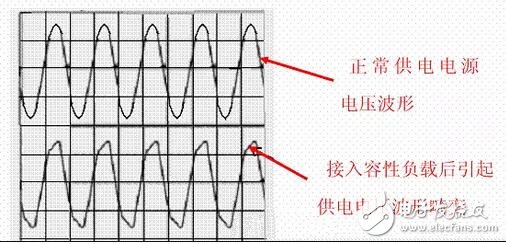
In the positive half cycle (1800), the conduction angle of the rectifier diode is much less than 1800 or even only 300-700. Due to the requirement of the load power, a large on-current is generated during the extremely narrow conduction angle. The power supply current in the power supply circuit is pulsed, which not only reduces the efficiency of the power supply, but more seriously, it generates severe AC voltage waveform distortion when the power supply line capacity is insufficient or the circuit load is large (Figure 3 ), and generate multiple harmonics, thus interfering with the normal operation of other electrical appliances (this is electromagnetic interference - EMI and electromagnetic compatibility - EMC problems).
figure 2

Since the electrical device has changed from the inductive load of the past (the early power supply of the TV, the radio, etc., the inductive device of the power transformer) to the capacitive load with the rectifying and filtering capacitors, the meaning of the power factor compensation is not only the power supply. The problem of different phases of voltage and current is more serious to solve the electromagnetic interference (EMI) and electromagnetic compatibility (EMC) problems caused by the strong pulse state of the supply current.
This is a new technology developed at the end of the last century (the background is due to the rapid development and widespread application of switching power supplies). Its main purpose is to solve electromagnetic interference (EMl) and electromagnetic compatibility (EMC) problems caused by severe distortion of the current waveform caused by capacitive loads. Therefore, the modern PFC technology is completely different from the past power factor compensation technology, which is adopted for the distortion of the non-sinusoidal current waveform, forcing the AC line current to track the instantaneous waveform of the voltage waveform, and keeping the current and voltage in phase, so that the system presents Pure resistive technology (line current waveform correction technique), this is PFC (Power Factor Correction).
Therefore, the modern PFC technology completes the correction of the current waveform and also solves the in-phase problem of voltage and current.
image 3
For the above reasons, it is required to use a capacitive load electrical appliance with an electric power greater than 85W (some data shows greater than 75W). It is necessary to add a correction circuit to correct its load characteristics so that its load characteristics are close to resistivity (voltage and current waveforms are in phase). And the waveform is similar). This is the modern power factor correction (PFC) circuit.
Kara offers a wide range of illuminated and non-illuminated Rocker Switches.Ranging from 4 to 9poles,16VA to 30 amp,with many styles of colors and functions,especially the switches with High-Current and some types which meet the industry standard IP65,IP68. Certifications include UL, CSA, TUV, CE, and more.

Middle-Sized Rocker Switches,Middle Rocker Switches,Economic Middle-Sized Rocker Switches,Universal Middle-Sized Rocker Switches
Ningbo Kara Electronic Co.,Ltd. , https://www.kara-switch.com