Cree XLamp® High Power Devices Latest Application Guidelines and Points to Watch Updates
——XB-D LED and XT-E LED optical design
Cree XLamp ® XB-D LEDs and XT-E LEDs are based on Cree's latest SC3 technology platform. At the heart of Cree SC3 technology is a new generation of Direct Attach (DA) silicon chip with higher light and light efficiency and better reliability. While XLamp ® XB-D LEDs and XT-E LEDs offer higher performance, special DA chip structures present challenges for optical design. This article describes these challenges and provides a means to effectively overcome them.
First, the DA chip
As shown in Figure 2, the silicon carbide substrate produces fewer dislocations than the sapphire substrate. Each dislocation creates a tiny black dot on the surface of the chip. Fewer dislocations mean fewer black dots, brighter, higher lumen output, ie higher efficiency (lm/w). These advantages combined with the DA chip have a 5-10% improvement in light efficiency compared to sapphire substrates. Another advantage is that there are fewer epitaxial defects and the LEDs produced are more reliable. The DA chip structure therefore provides higher light output, robustness, reliability and manufacturability.
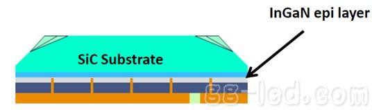
Figure 1 DA chip side view 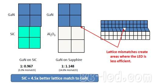
Figure 2 lattice mismatch comparison
Second, XLamp® XB-D LED and XT-E LED optical model
Cree XLamp ® XB-D and XT-E white LEDs are based on DA chips, and their optical models have some special optical properties that are distributed in a Lambertian light pattern. As seen from the schematic diagram 3 of the DA chip, in order to maximize the light output, cutting at the oblique side of the top surface of the chip poses a challenge to the secondary optical design of the LED. Due to the special cutting of the DA chip, the phosphor is deposited on the beveled cutting surface above the SiC.
For the XP series products using the EZ chip, blue light and yellow light are emitted from almost the same side. For products using the DA chip, similar to the small-sized remote phosphor structure, blue light is emitted from the InGaN epitaxial layer, and yellow light is emitted from the beveled cutting surface of the top surface of the DA chip. When designing a small angle of secondary optics, the light intensity is There may be some unevenness in the color distribution. Figures 4 and 5 show how light is produced from XLamp ® XP LEDs (EZ chips) and XB-D LEDs, XT-E LEDs (DA chips).
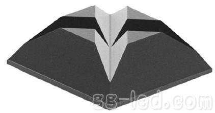
Figure 3 Schematic diagram of the DA chip 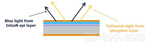
Figure 4 Schematic diagram of the EZ chip emitting light 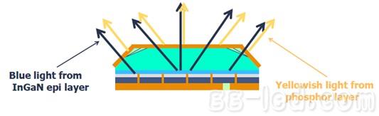
Figure 5 Schematic diagram of the light emitted by the DA chip
In order to improve the light output, there is a bevel cut on the top surface of the DA chip, which results in inconsistent phosphor thickness on the chip. Figure 6 is a near-field diagram of the XT-E LED when it is lit, paying attention to the yellow cross at the center of the figure, which indicates a thicker phosphor layer on the cross.
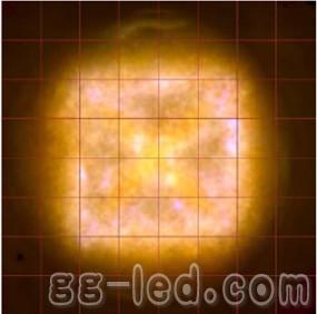
Figure 6 Near-field diagram of DA chip white LED
Third, LED secondary optical foundation
If the light distribution of the LED does not meet the specific application requirements, it is necessary to use secondary optics to change the light distribution of the LED so that the light distribution of the finished lamp meets the requirements. Secondary optics can also be used to improve color and light distribution uniformity in the target area. LED secondary optics are classified as follows: 1. Reflector, reflector 2. Lens 3. Combine lenses and reflectors, such as total reflection lenses (TIR) ​​4. Diffuser. Each optical system controls light in different ways, with different manufacturing techniques and prices. The main functions of LED secondary optics:
1) Collimation: Make most of the light most likely to shine on the target, such as a flashlight or a spotlight.
2) Diffusion: Let light spread or hide at a larger angle, blurring LED light sources, such as linear lamps or LED bulbs.
3) Illumination: illuminate light on a specific area without illuminating other areas, such as street lights or area lights.
Parabolic reflectors are very effective in collimating light and are easier to manufacture and less expensive than conventional lenses. However, the reflector has only one surface control beam, and many of the light emitted from the light source is directly emitted without being reflected by the reflective surface. The light reflected by the reflective surface is controlled and collimated, and the light that is not reflected by the reflective surface is not controlled. These lights are called spilled light.
Conversely, conventional lenses provide good control of the light at the center of the beam, but due to lens size issues, it is not possible to control light at large angles. TIR lenses are secondary optics that combine the advantages of reflectors and conventional lenses:
1) It can control both direct and reflected light 2) Make the light pass at least 2 faces before leaving the system 3) Even if the lens size is small, it will be very effective 4) Relatively high reflective glass price
As shown in Figure 7, the TIR lens comprises a total reflection (TIR) ​​face and a refractive lens. The refractive lens controls the light in the middle of the LED beam, and the TIR surface controls the light at a large angle.
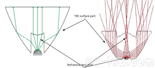
Figure 7 TIR lens
As mentioned earlier, the XLamp ® XB-D LED and XT-E LED use a DA chip, which makes the color uneven at small angles. For TIR lenses, the methods for mixing colors are:
1. The top surface of the lens is frosted or the microlens is added, as shown in Figures 8 and 9. If the added microstructure is too much, the angle of the light will be too large, and too much light will be lost. Conversely, too little color mixing will be uneven.
Figure 8 frosted surface (provided by Ledil) 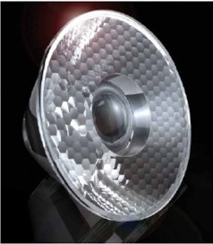
Figure 9 Microstructure (provided by Gaggione)
2. Add a diffusion structure to the refractive lens, as shown in Figure 10.
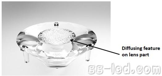
Figure 10 diffusion structure (provided by Illumination Machines)
3. The TIR surface adds a diffusion structure as shown in FIG.
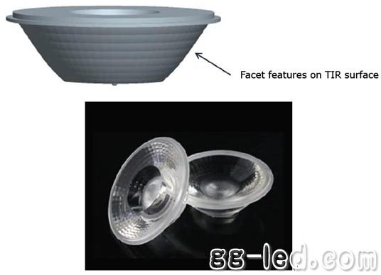
Figure 11 Diffusion structure on the TIR surface (provided by Ledlink)
XRX can produce many serials of PLC splitters including
1X2, 1X4, 1X8, 1X16, 1X32, 1X64, 2X4, 2X8, 2X16, 2X32, 2X64 with following package,
Bare Fiber PLC Splitters
Blockless Fiber Optical PLC Splitter
ABS box Fiber Optic PLC Splitter
LGX Box Optical PLC Splitters
Cassette Box PLC Splitter
Pallet Type Optical Fiber PLC Splitter
Rack Mount PLC Splitter for PON application
Wall Mount PLC Splitters
Rack type: installed in 19 inch OLT cabinet; in fiber branch home, the installation equipment is standard digital cabinet; when ODN need to be placed on the table.
Cassette type: installed in 19 inch standard rack; in fiber branch home, installation device is provided in the optical fiber cable transfer box; branch home, installed customer specified equipment.
Branch type: installed in various types of optical distribution equipment. Installed in various types of optical testing instruments.
Miniature: installed in optical cable connector box. Installed in the module box. Installed in the wiring box.
Insert: This equipment is used for user access point for optical FTTX system, mainly to complete the cable into the area or building into the end, with a fixed, stripping, welding, and other functions of the shunt jumper, optical fiber, light to form a cable into the terminal user.
Tray type: Fiber Optic Splitter, applicable to various types of wave division multiplexer integrated installation.
Planar lightwave circuit splitter (PLC Splitter) is a kind of integrated waveguide optical power distribution device based on quartz substrate. It has the advantages of small volume, wide bandwidth, high reliability, excellent uniformity. Optical Fiber Splitter is especially suitable for passive optical networks (EPON, BPON, GPON) which is connected with the terminal equipment and realize the optical power distribution.
XRX provides 1*N and 2*N fiber optic splitters. And these PLC splitters can be made as per customer request.
PLC Splitter,Fiber Optic PLC Splitter,Optical Cable Splitter,PLC Optic Splitter
Chengdu Xinruixin Optical Communication Technology Co.,Ltd , https://www.xrxoptic.com