In digital circuit experiments, several instruments and instruments are needed to observe experimental phenomena and results. Commonly used electronic measuring instruments include multimeters, logic pens, ordinary oscilloscopes, storage oscilloscopes, and logic analyzers. The use of multimeters and logic pens is relatively simple, and logic analyzers and storage oscilloscopes are currently not widely used in digital circuit teaching experiments. An oscilloscope is a very widely used instrument that is relatively complex to use. This chapter introduces the principle and usage of the oscilloscope from the perspective of use.
1 How the oscilloscope works
An oscilloscope is an electronic measuring instrument that utilizes the characteristics of an electronic oscilloscope to convert an alternating electrical signal that cannot be directly observed by the human eye into an image and display it on a fluorescent screen for measurement. It is an important instrument for observing the experimental phenomena of digital circuits, analyzing problems in experiments, and measuring the results of experiments. The oscilloscope consists of an oscilloscope and power system, a synchronization system, an X-axis deflection system, a Y-axis deflection system, a delay scanning system, and a standard signal source.
1.1 oscilloscope
Cathode ray tube (CRT) is called the oscilloscope tube and is the core of the oscilloscope. It converts electrical signals into optical signals. As shown in Figure 1, the electron gun, deflection yoke and screen are sealed in a vacuum glass envelope to form a complete oscilloscope tube.
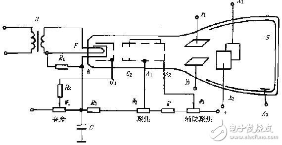
Figure 1 shows the internal structure of the oscillating tube and the power supply
1. Fluorescent screen
The current oscilloscope screen is usually a rectangular plane, and a phosphor film is deposited on the inner surface to form a fluorescent film. A layer of evaporated aluminum film is often added to the fluorescent film. High-speed electrons pass through the aluminum film and strike the phosphor to illuminate to form a bright spot. The aluminum film has an internal reflection effect, which is advantageous for increasing the brightness of the bright spot. The aluminum film also has other effects such as heat dissipation.
When the electrons stop bombardment, the bright spots cannot disappear immediately and remain for a while. The time elapsed after the brightness of the bright spot drops to 10% of the original value is called "afterglow time". The afterglow time is shorter than 10μs for very short afterglow, 10μs-1ms for short afterglow, 1ms-0.1s for medium afterglow, 0.1s-1s for long afterglow, and greater than 1s for extremely long afterglow. The general oscilloscope is equipped with a medium afterglow oscilloscope, the high frequency oscilloscope uses a short afterglow,
Due to the different phosphorescent materials used, different colors of light can be emitted on the screen. Generally, oscilloscopes use green light-emitting oscilloscopes to protect people's eyes.
2. Electron gun and focus
The electron gun is composed of a filament (F), a cathode (K), a grid (G1), a front accelerating pole (G2) (or a second grid), a first anode (A1), and a second anode (A2). Its role is to emit electrons and form very fine high-speed electron beams. The filament energizes the cathode and the cathode emits electrons by heat. The grid is a metal cylinder with a small hole at the top and is placed outside the cathode. Since the gate potential is lower than that of the cathode, the electrons emitted from the cathode are controlled. Generally, only a small amount of electrons having a large initial velocity of movement can pass through the gate aperture and rush to the phosphor screen under the action of the anode voltage. Electrons with a small initial velocity still return to the cathode. If the gate potential is too low, all of the electrons return to the cathode, ie the tube is turned off. Adjusting the W1 potentiometer in the circuit can change the gate potential and control the electron flux density that is directed to the screen to achieve the brightness of the bright spot. The first anode, the second anode, and the front accelerating pole are all three metal cylinders on the same axis as the cathode. The front accelerating pole G2 is connected to A2, and the applied potential is higher than A1. The positive potential of G2 accelerates the cathode electrons toward the phosphor screen.
The electron beam travels from the cathode to the phosphor screen and undergoes two focusing processes. The first focus is done by K, G1, G2, and K, K, G1, G2 are called the first electron lens of the oscilloscope. The second focus occurs in the G2, A1, and A2 regions, and the potential of the second anode A2 is adjusted so that the electron beam can just converge on the phosphor screen, which is the second focus. The voltage on A1 is called the focus voltage, and A1 is called the focus pole. Sometimes adjusting the A1 voltage still does not satisfy the good focus. The voltage of the second anode A2 needs to be fine-tuned. A2 is also called the auxiliary focus pole.
3. Deflection system
The deflection yoke controls the direction of the electron beam so that the spot on the screen draws the waveform of the signal under test as a function of the applied signal. In Figure 8.1, two pairs of mutually perpendicular deflection plates, Y1, Y2 and X1, X2, form a deflection yoke. The Y-axis deflection plate is in front and the X-axis deflection plate is behind, so the Y-axis sensitivity is high (the measured signal is processed and added to the Y-axis). The two pairs of deflection plates are respectively applied with voltages to form an electric field between the two pairs of deflection plates, respectively controlling the deflection of the electron beams in the vertical direction and the horizontal direction.
4. Oscilloscope power supply
In order for the oscilloscope to work properly, there are certain requirements for the power supply. It is prescribed that the potential between the second anode and the deflector is similar, and the average potential of the deflector is zero or close to zero. The cathode must operate at a negative potential. The gate G1 is at a negative potential (-30V~-100V) with respect to the cathode, and is adjustable to achieve luminance adjustment. The first anode is a positive potential (about +100V~+600V) and should also be adjustable for use as a focus adjustment. The second anode is connected to the front accelerating pole, and has a positive high voltage (about +1000 V) to the cathode, and an adjustable range of ±50 V with respect to the ground potential. Since the electrodes of the oscilloscope have a small current, they can be supplied with a common high voltage via a resistor divider.
1.2 Basic components of the oscilloscope
As can be seen from the previous section, as long as the voltages on the X-axis deflector and the Y-axis deflector are controlled, the shape of the oscilloscope display can be controlled. We know that an electronic signal is a function of time f(t) that changes with time. Therefore, as long as a voltage proportional to the time variable is added to the X-axis deflection plate of the oscilloscope, and the signal to be measured is added to the y-axis (proportional amplification or reduction), the measured on the oscilloscope screen will be displayed. A graph of the signal as a function of time. In an electrical signal, the signal proportional to the time variable over a period of time is a sawtooth wave.
The basic block diagram of the oscilloscope is shown in Figure 2. It consists of five parts: oscilloscope, Y-axis system, X-axis system, Z-axis system and power supply.
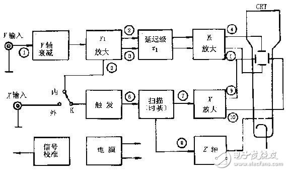
Figure 2 oscilloscope basic composition block diagram
The signal to be tested 1 is connected to the "Y" input terminal, and is appropriately attenuated by the Y-axis attenuator and then sent to the Y1 amplifier (preamplifier) ​​to push-pull the output signals 2 and 3. The delay stage is delayed by Г1 time to the Y2 amplifier. Amplification produces a sufficiently large signal 4 and 5 to be applied to the Y-axis deflection plate of the oscilloscope. In order to display a complete stable waveform on the screen, the signal D of the Y-axis is introduced into the trigger circuit of the X-axis system, and a trigger pulse 6 is generated at a certain level of the positive (or negative) polarity of the incoming signal, and the trigger pulse 6 is activated. A sawtooth scanning circuit (time base generator) generates a scanning voltage of 7. Since there is a time delay Г2 from the trigger to the start of the scan, the delay time Г1 of the Y-axis should be slightly larger than the delay time Г2 of the X-axis to ensure that the X-axis starts scanning before the Y-axis signal reaches the screen. The scan voltage 7 is amplified by an X-axis amplifier to produce push-pull outputs 9 and 10 which are applied to the X-axis deflection plate of the oscilloscope. The z-axis system is used to amplify the sweep voltage forward and become a forward rectangular wave that is sent to the oscilloscope gate. This causes the waveform displayed in the scan forward to have a certain fixed luminance, while the scanning backhaul is smeared.
The above is the basic working principle of the oscilloscope. The dual trace display uses the electronic switch to display two different measured signals input to the Y axis on the screen. Due to the visual persistence of the human eye, when the switching frequency is high to a certain extent, two stable and clear signal waveforms are seen.
There is often an accurate and stable square wave signal generator in the oscilloscope for calibration oscilloscopes.
simple hanging lighting is suitable for home decoration, 5 star hotel, project such as mansion, villa or bar and so on it is also suitable for matching with furniture at home.
simple hanging lamp,Indoor decoration light are our main products. Meanwhile, we provide some other products, such as ceiling light and Wall Lamp .
simple hanging lamp,simple hanging light,simple hanging lighting
Monike lighting , https://www.monikelight.com